
Mastering the Basics: How a Full-Wave Bridge Rectifier Converts AC to DC
Understanding the Full-Wave Bridge Rectifier
Have you ever wondered how the devices you plug into a wall outlet—running on Alternating Current (AC)—manage to power internal components that require Direct Current (DC)? Whether it’s your laptop charger or a guitar amplifier, the answer often lies in a fundamental electronic circuit: the Full-Wave Bridge Rectifier.
In this post, we’ll demystify this essential circuit by breaking down its components and explaining how it “steers” electricity to power your devices efficiently.
The Goal: What Is Rectification?
Rectification is the process of converting AC (where voltage and current direction periodically reverse) into DC (where voltage and current flow in one constant direction).
While a single diode can block half of the AC signal (half-wave rectification), it wastes energy. The
Full-Wave Bridge Rectifier is a smarter solution. It uses four diodes arranged in a specific pattern to convert both the positive and negative halves of the AC waveform into usable DC energy.
The Circuit Diagram
This arrangement is commonly referred to as a diode bridge.

Key Components
- AC Input (The Source):
Represented by a circle with a sine wave (~). This is your voltage source (often from a transformer) that swings between positive and negative voltage. - The Diode Bridge (D1, D2, D3, D4):
This diamond-shaped arrangement is the heart of the circuit. The four rectifier diodes act like electrical “check valves,” allowing current to flow in only one direction. - The Load (RLoad):
Represented by a resistor symbol. This is the device being powered. - DC Output (+V and 0V):
These are the terminals where rectified current exits to power the load.
How It Works: The “Steering” Mechanism
The brilliance of the full-wave bridge rectifier is that no matter which way the AC input pushes current, it always forces the current to flow through the load in the same direction.
1. The Positive Half-Cycle
- D1 becomes forward-biased and conducts current to the top of the load.
- The current flows down through the load.
- D2 returns the current to the negative side of the source.
Result: Current flows Top → Bottom through the load.
2. The Negative Half-Cycle
- D3 becomes forward-biased and conducts current to the top of the load.
- The current again flows down through the load.
- D4 returns the current to the source.
Result: Current still flows Top → Bottom through the load.
Why Use a Bridge Rectifier?
- Higher Efficiency: Uses the entire AC waveform—no half wasted.
- Smoother Output: Reduced gaps between pulses reduce ripple.
- Cost-Effective: Only four diodes required and no center-tapped transformer needed.
Next Steps: Smoothing the Signal
While the output is DC, it is still “pulsating.” To turn this into a steady voltage for sensitive electronics, designers add a smoothing capacitor in parallel with the load. This capacitor fills in the gaps between the peaks of the rectified waveform, producing a cleaner, more stable DC output.
Recommended Components for Your Rectifier Projects
Here are some essential diode components you may need for building or experimenting with AC-to-DC rectifier circuits. All are available at Oku Electronics.

Bridge Rectifier Diode – 25A, 1000V (4-Pin)
₵12.00 — High-power diode bridge ideal for AC to DC conversion.
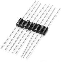
1N4001 – 1A Rectifier Diode (10pcs)
₵3.00 — A reliable diode for low-power rectification and protection circuits.
1N5400 – 3A Power Diode (10pcs)
₵10.00 — Stronger diode suitable for high-current rectifier circuits.
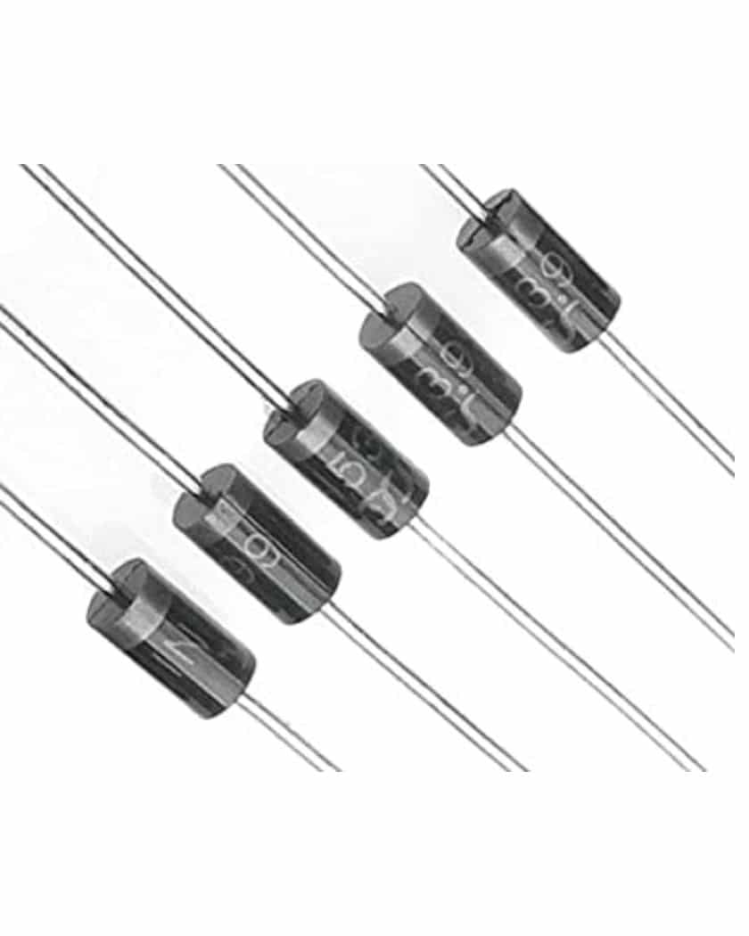
1N5399 – 1.5A Diode (10pcs)
₵4.00 — A versatile mid-range diode useful for many rectifier projects.